


Cz and LEC of III-VS
高压液态封装 Cz 法生长


InP 的高压液体封装 Czochralski(HPLEC)法生长
与传统的 Czochralski 法工艺不同,高压液体封装 Czochralski(HPLEC)法的建模特别复杂,因为必须考虑到湍流气体和熔体对流以及防止磷从熔体中蒸发的封装剂。再循环气体、B2O3 层和晶体之间的传热相互作用非常复杂,需要特别精确的模拟。
为了研究气体流动对晶体内热场的影响,我们使用了三维非稳态模型,该模型可以直接解析湍流漩涡及其对热交换的影响。我们考虑了工业 HPLEC InP 装置中的气体对流以及晶体和封装流中的热传导,特别关注晶体中的温度梯度,因为它们决定了热应力。


Figure 1. Computational domain for preliminary 2D steady-state Figure 2. Computational domain for detailed 3D
simulation of global heat transfer with the unsteady simulations
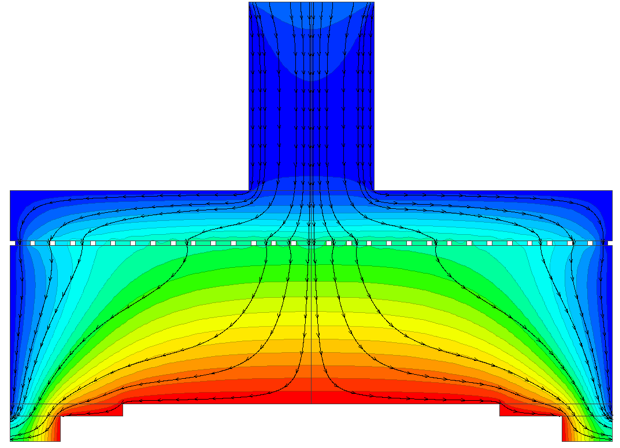
computed temperature distribution and flow pattern
计算过程包括对整个装置(图1)的全局传热进行初步模拟,并使用二维轴对称稳态模型对所有热交换模式(对流、辐射和传导)进行计算。得出的热场用于设置三维计算域的边界条件,见图2。
结果表明,在计算域的不同区域存在多尺度涡旋的非轴对称流动结构。解决方案的总体特征是沿拉杆向上流动,沿冷却外壁向下流动,以及晶体和坩埚之间区域的两个再循环区,在晶体和拉杆周围的生长装置中心观察到最密集的非稳定对流,见图3(a、b)。


Figure 3 (a). Instantaneous flow patterns and Figure 3 (b). Instantaneous flow patterns and
temperature distributions in the gas domain temperature distributions in the gas domain
at two different time moments. at two different time moments.
气体中强烈的温度波动导致晶体外围温度和温度梯度的明显变化。从图4和图5中可以看出,最大的绝对梯度出现在熔体/晶体/胶囊剂三交点,而出现较大径向梯度的区域位于晶体/胶囊剂/气体三交点。此外,晶体圆锥部分的径向温度梯度波动会导致位错倍增。


Figure 4. Instantaneous distributions of the Figure 5. Instantaneous distributions of the
absolute temperature gradients at the two time moments. radial temperature gradients at the two time moments.
为了估算气体对流对晶体表面热损失的贡献,我们比较了晶体和封装材料在不同状态下的时间平均热通量,如图6和图7所示。可以看出,由于湍流气体对流的影响,晶体和封装体的热损失随着气体压力的增加而急剧增加。在二维准稳轴对称方法中使用两种不同的湍流模型进行的类似计算大大低估了晶体和封装材料的热损失。总之,晶体周围的氮气流极大地影响了晶体的轴向温度梯度,此外,还会在晶体的圆锥部分产生可观察到的径向温度梯度不稳定波动,从而导致位错密度显著增加。因此,在分析缺陷形成和优化生长过程时,必须准确考虑非稳定气体对流。由于二维模型通常会严重低估晶体的气体冷却,因此要充分描述气体对流效应,就必须进行三维非稳态分析。


Figure 6. Average heat fluxes across the crystal surface Figure 7. Average heat fluxes across the encapsulant surface,
computed with the 3D unsteady (solid lines) computed with the 3D unsteady (solid lines)
and 2D steady (dashed and dash-dotted lines) models. and 2D steady (dashed and dash-dotted lines) models.
References
[1] “Prediction of the melt/crystal interface geometry in liquid encapsulated Czochralski growth of InP bulk crystals”, E.N. Bystrova, V.V. Kalaev, O.V. Smirnova, E.V. Yakovlev, Yu.N. Makarov, J. Crystal Growth, 250 (2003) pp. 189–194.
[2] “3D unsteady analysis of gas turbulent convection during HPLEC InP growth”, E.N. Bystrova, V.V. Kalaev, J. Crystal Growth, 287 (2006) pp. 275–280.

